
Guide
Commissioning, measurement and balancing of ventilation systems
A ventilation system that has only been installed will not deliver the airflow calculated in the design until it has been measured and adjusted. This guide explains what is checked before commissioning, how fan speed and rotation are verified, how airflow is measured at grilles and in ducts, how balancing is done with dampers, and what the handover report should contain.
What are commissioning and testing, adjusting and balancing?
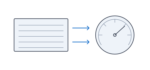
Commissioning means running a ventilation system for the first time after installation and demonstrating, by measurement, that it actually delivers the values required by the design. The most important part of this work on site is known as testing, adjusting and balancing (TAB for short, in Turkish test-ayar-balans): the system is tested, the fans and dampers are adjusted, and the air is balanced so that every space receives its design airflow.
This step is often treated as a minor addendum to installation, yet the outcome depends directly on it. In a duct network, air always takes the path of least resistance: grilles close to the fan receive too much air and those far away receive too little. However accurately the design has been calculated, in an unbalanced system some rooms are left short of air while others suffer from draughts and noise complaints. In areas where pressure relationships are required, such as hospitals and clean rooms, an unmeasured system is also a hygiene risk.
In brief
- The system is started up; the fan's rotation, speed and current draw are checked.
- Airflows are measured in the ducts and at the grilles, and brought to the design values with dampers.
- Pressures are measured, the results are reported and the system is handed over in its adjusted state.
How are measurement and balancing carried out?
Measurement starts at the fan and works along the duct towards the grilles. The diagram below shows what is measured where on a simple supply line:
- Fan. First, the direction of rotation, the speed and the current drawn by the motor are checked. The fan determines the total airflow and pressure of the system, and all other adjustments are made on that basis.
- Static pressure measurement. Pressures taken at the fan inlet and outlet show the point at which the fan is operating against the duct network. The difference across the filters, before and after, is measured in the same way.
- Airflow measurement in the main duct. A pitot tube is inserted through measurement holes drilled in a straight duct section, and velocity is measured at many points across the cross-section (a traverse). This measurement gives the total air delivered by the fan to the system.
- Balancing dampers. By throttling the dampers on the branches, the air is shared between the branches in line with the design proportions. The dampers are set according to the measurement results and their positions are marked.
- Grille measurement. The air leaving each grille or diffuser is measured with an airflow hood (balometer) or an anemometer and compared with the design value.
A difference between the total airflow measured in the main duct and the sum of the airflows measured at the grilles points to duct leakage or to an outlet that has not been measured. This comparison is also the most practical way to see whether the measurements are consistent with one another.
Which systems need it?
Every ducted ventilation system should be measured and adjusted. In some applications, however, this step is even more important:
- Hospitals and clean rooms: In operating theatres, intensive care units and isolation rooms, both the airflow and the pressure difference between rooms (positive or negative) are measured and verified.
- Offices, schools and meeting rooms: The fresh air per person is calculated in the design; without balancing, rooms far from the fan receive too little air.
- Shopping centres and large commercial buildings: Imbalance is more pronounced in long duct networks with many branches.
- Factories and workshops: If local extract points do not achieve sufficient velocity, fumes, dust and vapour spread into the space.
- Commercial kitchens: The balance between hood extract and fresh air keeps the kitchen at a slightly negative pressure, so that odours do not carry into the dining area.
- Car park and tunnel ventilation: The direction and airflow of the fans, and their operation in line with the scenarios, are tested during commissioning.
Measurement methods and instruments
Which instrument is used depends on where the measurement is taken and on the air velocity. The most commonly used on site are as follows:
Pitot tube and micromanometer
Measures the dynamic pressure in the duct, from which velocity is calculated. It is the basic method for in-duct airflow measurement; reading accuracy decreases at low velocities.
Thermal (hot-wire) anemometer
Measures low air velocities accurately. It is used for duct traverses, on filter faces and in clean rooms.
Vane anemometer
Measures the average velocity across the face of a grille or louvre. To convert this to airflow, the effective area of the grille and the manufacturer's correction factor are needed.
Airflow hood (balometer)
Placed over the grille, it reads the airflow directly in m³/h. It is the most reliable grille measurement for swirl and ceiling diffusers.
Dampers with measuring nozzles and measurement stations
The pressure difference is read at iris dampers or measurement stations, and the airflow is calculated with the factor supplied by the manufacturer.
Tachometer and clamp ammeter
Fan speed is measured with an optical tachometer and motor current with a clamp ammeter, and both are compared with the nameplate values.
In pitot measurement, velocity is calculated from the dynamic pressure and the air density (v = √(2·pd/ρ)). The measurement plane should be chosen in a straight duct section sufficiently far from bends, dampers and branches; otherwise the velocity profile is irregular and an average taken from a few points is misleading. The cross-section is divided according to a method that determines the positions of the measurement points (one commonly used on site is the log-Tchebycheff method), and the reading at each point is recorded separately.
At grilles, the type of grille is decisive. With swirl or multi-directional ceiling diffusers, a reading taken from the face with a vane anemometer is generally unreliable; these grilles are measured with an airflow hood. The hood also adds resistance in front of the grille, so some instruments include a back-pressure compensation that offsets this effect.
Balancing with dampers
The aim of balancing is to distribute the air correctly without making the fan work unnecessarily hard. The most widely used approach on site is the proportional balancing method. The basic idea is this: when you throttle one grille on a branch, the airflow of the others also changes, but the ratio of the grilles to one another is largely maintained.
- Preliminary measurement. With all dampers fully open, the airflow at each grille is measured and its ratio to the design airflow (measured ÷ design) is calculated.
- Finding the index grille. On each branch, the grille with the lowest ratio is identified. This is usually the grille furthest from the fan, and its damper is left fully open.
- Balancing within a branch. The other grilles on the branch are throttled until their ratios match that of the index grille. Adjustment starts at the point furthest from the fan and works towards the fan.
- Balancing between branches. Following the same logic, the branch dampers are adjusted so that the ratios of the branches to one another are equalised.
- Fan adjustment. Once all the ratios are equal, the fan speed is increased or reduced so that the total airflow reaches the design value. Because the ratios are maintained, all the grilles approach their design values together.
- Verification measurement and marking. Final measurements are taken and the damper positions are marked or locked.
It is important that at least one damper on every air path remains fully open. If the target airflow is reached by throttling all the dampers, the system carries unnecessary resistance; the fan delivers the same air at a higher pressure, using more energy and making more noise. Excess airflow should be reduced by fan speed, not by dampers. According to the fan laws, airflow varies in direct proportion to speed, pressure with the square of the speed and power with approximately the cube of the speed; reducing speed is therefore far more efficient than throttling a damper.
Values measured during commissioning
The main values measured and recorded before handover are as follows:
| Value | Why is it measured? |
|---|---|
| Total airflow (m³/h) | Shows whether the air delivered by the fan to the system meets the design value. It is measured in the main duct by traverse. |
| Grille airflows (m³/h) | Shows whether each space receives its design airflow. The result of the balancing is assessed with these values. |
| Fan speed (rpm) and motor current (A) | Shows that the fan is running at the correct speed and that the motor is not overloaded. The current is compared with the nameplate value. |
| Fan inlet and outlet static pressure (Pa) | Determines the operating point of the fan. If it is much higher than the design anticipated, there is a blockage in the duct, a closed damper or an unexpected resistance. |
| Filter pressure difference (Pa) | The initial value of the clean filter is recorded; any later decision to replace it is made on the basis of this value and the manufacturer's final value. |
| Pressure difference between rooms (Pa) | In operating theatres, isolation rooms and clean rooms, confirms that air flows from clean to dirty areas. |
| Fresh air and extract balance | Ensures that the building or section remains at the required pressure (slightly positive or negative). |
| Air temperatures and sound (if required) | Where a coil is fitted, the supply temperatures are checked; in sensitive spaces, the sound level is checked. |
How far a measured value may deviate from the design value is assessed against the tolerance range stated in the technical specification of the project. In Europe, the test and measurement methods for the handover of ventilation systems are defined in EN 12599; ASHRAE Standard 111 is also a frequently used reference for measurement, testing, adjusting and balancing. Which standard and which tolerance will apply should be agreed at the start of the job with the design and specification.
On site: from pre-checks to handover
Before measurement begins, the system must be ready to be measured. Balancing carried out on an incomplete installation has to be repeated from scratch once the deficiency is put right. The main pre-checks are:
- The ductwork installation is complete, the access covers are closed and the inside of the duct is clean, so that construction dust is not drawn into the system,
- The filters are fitted (measurements are taken with clean filters, and filters used during the construction period are replaced),
- The balancing, fire and smoke dampers are in the open position, and the grilles and diffusers are in place,
- The fan's anti-vibration mounts, flexible connections, belt tension and pulley alignment are checked,
- The electrical connections, the motor protection and, where fitted, the frequency converter settings are checked,
- The fan is run briefly and its direction of rotation is compared with the arrow on the casing.
The direction of rotation is particularly important. A centrifugal fan running in reverse still moves the air in the same direction, but at a much lower airflow; it is therefore not enough merely to check that air is coming out of the grille. On three-phase motors, the direction is corrected by swapping two of the phases. Once the direction has been verified, speed and current are measured, followed by the pressure and airflow measurements.
The instruments used for measurement must have valid calibration, which should be recorded in the report together with the list of instruments. The handover report generally includes the following: the design and measured airflow for each grille, the main duct traverse results, the fan speed, motor current and pressure values, the initial filter pressure differences, the pressures between rooms where required, and the final damper positions. This report is the baseline for comparison if a complaint or a change arises in the system in future.
At HSS Mekanik, we start up the system, measure the airflows at the grilles and hand it over in working order with the dampers adjusted.
Frequently asked questions
If air is coming out of the grille, does that mean the system is working correctly?
No. Air coming out only shows that the fan is running. Whether each space receives its design airflow can only be established by measurement. In systems that have not been balanced, grilles close to the fan receive too much air and distant grilles too little; even a fan running in reverse can deliver some air through the grilles.
If the airflow is too high, isn't throttling the dampers enough?
The most efficient way to reduce airflow is to reduce the fan speed. Throttling with dampers puts extra resistance on the fan; the fan uses more energy and the noise increases. Dampers should be used to share the air between branches and grilles.
Is it enough to balance once?
The adjustment is maintained for as long as the system is not changed. However, if a space is partitioned, a new grille is added, the ductwork is altered or the fan is replaced, the section concerned should be measured and balanced again. The values in the handover report are the starting point for this comparison.
Can the building be in use during measurement?
It can, but the state of the doors, windows and other systems must be kept constant throughout the measurement. Pressure measurements between rooms in particular change as doors are opened and closed; these measurements are taken under normal operating conditions with the doors closed.
Applications where measurement and balancing are critical
See the systems used in these applications, with drawings.