
Guide
Ductwork fabrication and installation
However well the air handling unit or fan is selected, the system will not deliver the expected performance if the duct that carries the air to the space is poorly made. This guide explains how galvanised rectangular and spiral ducts are fabricated and joined, how sealing and insulation are achieved, and what to watch for during installation.
What is ventilation ductwork?
Ventilation ductwork is the air path that carries the air prepared by an air handling unit, fan or heat recovery unit to the spaces, and carries the air drawn from the spaces back to the unit or outside. Fresh air, exhaust, return and smoke extraction lines are all built from ducts. In a building they usually run above the suspended ceiling, in shafts, or exposed in the space.
A duct may look like a simple sheet-metal pipe, but it directly determines system performance. A duct with an undersized cross-section causes excessive pressure loss and noise; a leaking duct lets part of the air escape into the ceiling void instead of reaching its destination; a duct with inadequate insulation causes condensation or loses energy. For this reason, duct fabrication and installation is work that is engineered together with its size, sheet, joints, hangers and insulation.
In brief
- Ducts carry air from the unit to the space, and from the space to the unit or outside.
- The most common material is galvanised steel sheet; rectangular and spiral (circular) cross-sections are used.
- Correct sizing, airtight joints, adequate insulation and sound hangers are what allow the system to work as designed.
What does a duct run consist of?
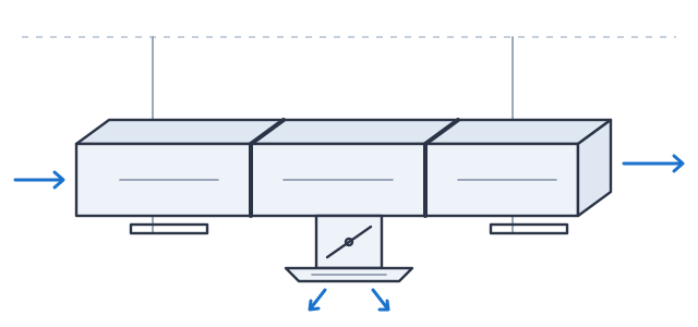
A typical run starts at the unit outlet and extends to the grille or diffuser in the space through straight duct sections, fittings, jointing components and hangers. The diagram below shows a side view of a supply run that starts with rectangular duct and continues in spiral duct:
- Flexible connection. The outlet of the air handling unit or fan is connected to the duct with a flexible connector, so that the unit's vibration is not transmitted to the duct and the building.
- Rectangular duct and flanged joint. Straight duct sections are connected to each other with flanges at their ends. The gaps between flanges are gasketed and the corners are closed with sealant.
- Trapeze hanger. Threaded rods fixed to the slab with anchors, together with a profile that passes under the duct, carry the duct.
- Transition piece. It changes from a rectangular to a circular cross-section (or from one size to another) at a gentle angle; an abrupt contraction creates pressure loss and noise.
- Spiral duct and gasketed joint. Spiral ducts are joined with fittings whose ends slot inside the duct; with gasketed fittings, a rubber gasket provides the seal.
- Clamp hanger. Circular duct is hung with a clamp attached to a threaded rod. A rubber insert used inside the clamp reduces vibration and noise transmission.
- Branch and balancing damper. A branch leaving the main run is taken off with a tee or saddle branch. The balancing damper on the branch allows the airflow to each space to be balanced during commissioning.
- Diffuser. Air is supplied to the space through a diffuser or grille selected according to velocity and throw distance.
In addition, the run includes fire dampers at fire compartment crossings, silencers where required, and access panels for cleaning and maintenance. Extract and return runs are built on the same principle, with the airflow in the opposite direction.
Where is ductwork used?
Every building in which air is supplied to several points from a central unit, or drawn from several points, has ductwork:
- Shopping centres, shops and supermarkets: Fresh air and return runs distributed across large sales areas; in spaces with open ceilings, often exposed spiral duct.
- Buildings such as offices, schools and hotels: Fresh air and extract runs that run within the suspended ceiling and branch to each room or zone.
- Factories and production facilities: High-airflow runs carried over long distances, process extract and dust extraction runs.
- Airports, sports halls and large halls: Large-diameter ducts leading to long-throw diffusers in high-ceilinged volumes.
- Commercial kitchens: Extract ducts that carry grease-laden air from the kitchen hood to the roof. These are built to different rules from galvanised ventilation ducts (we touch on this below).
Duct types
Rectangular galvanised duct
Can be fabricated in any size by cutting and bending galvanised sheet. It is the most flexible solution where ceiling void height is limited and for large cross-sections.
Spiral (circular) duct
Produced continuously by winding galvanised strip with a spiral lockseam. It is favourable for airflow, uses less sheet for the same cross-section and is easy to seal.
Flat oval spiral duct
A flattened form of spiral duct. It brings the advantages of circular duct to ceiling voids where height is limited.
Flexible duct
Flexible duct that makes the final connection from the main run to the diffuser. Because its pressure loss is high, it is laid short and taut; it is not used as a main run.
Stainless steel duct
Preferred in damp, corrosive or high-hygiene environments, and in extract runs where a galvanised coating would not last.
Kitchen extract duct
Because it carries greasy, hot air, it is generally made of welded, fully airtight steel sheet; it is dealt with together with cleaning access panels and fire safety rules.
Fabrication: sheet, joints and fittings
Material. Hot-dip galvanised sheet is the most widely used material for ventilation ducts. The zinc coating protects the steel from corrosion; the coating weight is specified in grams per square metre (for example, Z275 means a total of 275 g/m² of zinc on both faces). If the project specifies a coating class, the sheet is selected accordingly.
Logic of sheet thickness. Thickness is not chosen arbitrarily. For rectangular duct, the deciding factors are the dimension of the longer side and the pressure class in which the duct will operate: as the side gets larger and the pressure rises, thicker sheet is needed to prevent the sheet from bulging (or collapsing inwards under suction) and from vibrating and making noise. In practice, thickness in ventilation ducts generally varies between 0.5 mm and 1.2 mm; which thickness to use at which size is given in table form in the project or in the applicable specification. For spiral duct, thickness is determined by diameter; because a circular cross-section is naturally more resistant to pressure, thinner sheet may be sufficient for the same cross-sectional area.
Rigidity. On rectangular ducts with large sides, the surfaces are stiffened by cross-breaking (diagonal creasing) or beading. For very large cross-sections, external reinforcement profiles or tie rods passing through the duct are used in addition.
Longitudinal seams. The longitudinal joints at the corners of rectangular duct are generally made with a Pittsburgh lock formed on a machine; the sheet is folded, interlocked and closed. In spiral duct, the seam forms by itself as a spiral lockseam during production.
Transverse joints and flanges. The main methods of connecting duct sections to each other are as follows:
- TDC / TDF flange: The flange is formed by bending the duct's own sheet on a machine. Corner pieces are fitted to the corners, and opposing flanges are tightened with bolts at the corners and flange clips in between. Common on medium and large rectangular ducts.
- Profile flange: A separately fabricated galvanised flange profile is slipped onto the duct end and fixed. Used for large cross-sections and where higher strength is required.
- S-cleat and drive-slip joints: Joints made with sheet slip-on pieces instead of flanges, on rectangular ducts of small cross-section.
- Spiral duct connections: The male end of the fitting is slotted into the duct; with gasketed fittings, a double-lip rubber gasket provides the seal, while for ungasketed joints, sealant, rivets or screws are used. For large diameters, a flanged connection is preferred.
Fittings. Bends, reducers, tee and breeches branches, offsets (S-bends) and end caps are where the duct run changes direction and size; most of the pressure loss and noise arises here. On rectangular bends, a radiused bend is used where possible; where there is no room, a square bend with turning vanes inside. In spiral systems, bends are produced pressed or segmented; saddle branches are used to take off a branch from the main run.
Sizing and design considerations
The duct cross-section is found from the airflow to be carried and the permitted air velocity. As velocity rises the duct gets smaller, but pressure loss and noise increase; as velocity falls the duct gets larger and the need for sheet and space increases. For this reason, higher velocities are selected in main runs and lower velocities closer to the space. Methods such as constant velocity or equal friction are used for sizing, and the total pressure loss of the run is taken as the basis for fan selection. The airflow equivalent of a rectangular duct is expressed as an equivalent diameter; very flat ducts mean more friction and more sheet for the same cross-section.
| Parameter | What it tells you |
|---|---|
| Airflow (m³/h) | The amount of air to pass through the duct. Each branch is calculated according to the needs of the space it serves. |
| Air velocity (m/s) | Determines the cross-section, pressure loss and noise together. Kept low on runs close to the space. |
| Pressure loss (Pa) | The total resistance of straight duct, fittings, dampers and grilles. The fan is selected to overcome this resistance. |
| Pressure class | The positive or negative pressure at which the duct will operate. Determines sheet thickness and the need for reinforcement. |
| Air leakage class | The permitted air leakage. EN 1507 (rectangular) and EN 12237 (circular) define the classes and the test method for ducts. |
| Size series | EN 1505 governs the dimensions of rectangular ducts and EN 1506 those of circular ducts; standard diameters make fittings and accessories easier to match. |
| Insulation | The material and thickness that prevent heat loss and condensation, according to the temperature of the air carried and the environment the duct passes through. |
| Fire and maintenance | Fire dampers at fire compartment crossings; access panels for cleaning and inspection (EN 12097). |
In design, the duct's route through the building is at least as important as its size: clashes under beams and with sprinkler and cable trays, and with electrical and plumbing services, should be resolved from the start, and dampers and panels must remain accessible for maintenance.
Sealing, insulation and installation
Sealing. Leakage means the fan works for nothing and less air reaches the space. On rectangular ducts, longitudinal seams, corner pieces and flange joints are closed with sealant, and gasket tape is placed between flanges. Because the seam of spiral duct is already locked, leakage occurs mainly at the joints; gasketed fittings therefore make it easier to reach a high air leakage class. If a class is required in the project, a section of the run is blanked off and pressurised with a test device, and the measured leakage is compared with the value the class permits.
Insulation. In ducts carrying chilled air, if the outer surface falls below the dew point it leads to condensation, dripping and, in time, ceiling damage; these ducts must have continuous vapour-resistant insulation. Closed-cell elastomeric rubber foam, or stone wool and glass wool with an aluminium foil facing, are commonly used. Joints are taped, and the insulation continues without gaps at hanger and flange points. For ducts in external environments, the insulation is protected against rain, sun and impact with an aluminium or galvanised cladding. Insulation thickness is determined by calculation of heat loss and condensation control.
Hanging. Hangers are selected to safely carry the weight of the duct, its insulation and, where necessary, any deposits inside. Trapeze hangers made of threaded rod and profile are used for rectangular ducts, and clamps for spiral ducts. Hanger spacing is determined by duct size and the specification; additional hangers are placed near heavy points such as bends, branches and dampers. The duct is fixed directly to the structure, not to the hangers of other services; anchors are selected to suit the condition of the concrete and the load. Hangers with vibration isolators can be used on runs close to fans and air handling units.
Points of attention on site:
- Keeping ducts and fittings capped at the ends and clean until installation, so that construction dust does not get inside the duct,
- Seating the flanges properly, and running the duct line without drifting off axis or sagging,
- Laying flexible ducts short, taut and without sharp bends,
- Fitting fire dampers at the wall or slab crossing in accordance with the manufacturer's installation detail,
- Leaving access panels and balancing dampers in accessible locations,
- Measuring the airflow at the grilles during commissioning and balancing it with the dampers.
Kitchen extract ducts are dealt with separately from these rules: because grease build-up carries a fire risk, the duct is made welded and airtight, arranged so that grease can be collected, fitted with access panels and kept away from combustible materials. For these runs, the Regulation on Fire Protection of Buildings (Binaların Yangından Korunması Hakkında Yönetmelik) and the project requirements are the basis.
At HSS Mekanik, we fabricate galvanised ducts in our own workshop to the dimensions in the project, and install them with insulation, hanger and sealing details.
Frequently asked questions
Spiral duct or rectangular duct?
Where space allows, spiral duct is advantageous because it uses less sheet for the same cross-section, offers less resistance to airflow and is easy to seal. If ceiling void height is limited, the cross-section is very large or the run includes complex transitions, rectangular duct is the more flexible solution. In most projects, both are used together.
What determines duct sheet thickness?
It is determined by the longer side dimension and the pressure at which the duct will operate for rectangular duct, and by diameter for spiral duct. The sheet gets thicker as the side or diameter grows and as the pressure rises. Which thickness to use at which size is given as a table in the project or specification.
Does every duct need to be insulated?
No. Ducts carrying heated or cooled air are insulated to prevent heat loss and condensation; vapour-barrier insulation is essential, especially on cold air ducts. Fresh air ducts that carry outdoor air in winter also risk condensation as they pass through the indoor environment, so they are mostly insulated. An extract duct passing through a space at the same temperature does not always need insulation; the decision is made according to the calculation in the project.
Is a duct leakage test necessary?
If a leakage class is required in the project or specification, the test shows that the run meets that class. Testing is especially important in places where pressure balance matters, such as hospitals and clean rooms, and on long, high-pressure runs; leakage means both energy loss and insufficient air in the space.
How far can flexible duct be used?
Flexible duct is used only for the final connection from the main run to the diffuser. Because its inner surface is rough, pressure loss is high; when it is laid long, sagging or with sharp bends, airflow drops noticeably. For this reason it is kept short and taut.
Applications that use ventilation ductwork
See the systems used in these applications, with drawings.